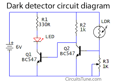
This is a basic dark detector/sensor circuit diagram based on a Photo Resistor (LDR) and few numbers of parts.
Parts list of dark detector:
R1 = 330Ω Resistor
R2 = 1KΩ Resistor
R3 = 1k Variable Resistor
Q1, Q2 = BC547 Transistor
One Photo Resistor (LDR)
One 6V DC power supply or Battery
R2 = 1KΩ Resistor
R3 = 1k Variable Resistor
Q1, Q2 = BC547 Transistor
One Photo Resistor (LDR)
One 6V DC power supply or Battery
Circuit diagram of dark detector/sensor:
 |
| Fig: Circuit diagram of dark detector/sensor |
When the LDR (Light Depended Resistor) is in light its resistance is low, and when in dark its resistance goes higher. When the light level decreases means the LDR is in darks then LDR goes its maximum threshold resistance, then the circuit automatically switches on the LED. Here I used a 1K variable resistor as R3 to adjust the dark/light sensitivity of the circuit.
Dark detector circuit using LDR, LED
 Reviewed by Shuvojit Das
on
7:36 AM
Rating:
 Reviewed by Shuvojit Das
on
7:36 AM
Rating:


Superb circuit. I made it with slight changes. Here are the changes.
ReplyDeletePower Supply - 5v (I have used an old battery bank with 2600 mAh)
R1 = 100 R - Enough for the light i need.
R2 = 1.5 K - Better dark sensing
R3 = 680 K - Better dark sensing.
Now this light will turn off when my room light is on (12W LED bulb). It will suddenly turn on the LED right after room lights turned off.