This is a simple ceiling fan regulator circuit diagram tutorial. It is used to control the speed of a ceiling fan. In the other words it is an AC motor speed controller circuit, as because it's control the speed of a AC motor(Ceiling Fan). This ceiling fan regulator circuit built with few numbers of parts. The circuit mainly based on Z0607 TRIAC. This is a low power AC semiconductor device. Generally which is used to controlling speed of low power ac motor speed.
Circuit Diagram of Ceiling Fan Regulator :
 |
| Fig: Ceiling fan regulator (AC motor speed controller) Circuit Diagram |
In this ceiling fan regulator circuit, R1=500KΩ is a variable resistor that is used to adjust the fan speed. Capacitor C1 2A104J is a Polyester film capacitor.
D1 = DB3 C312 -DIAC
R1 = 500KΩ -Variable Resistor
R2 = 37KΩ -Resistor
C1 = 2A104J -Polyester film capacitor.
M1 = Single Phase AC Motor (Ceiling Fan)-220V,50Hz
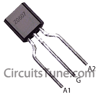
Pin Diagram of TRIAC(T1)- Z0607:
 |
| Fig: Z0607-TRIAC Pin diagram |
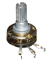
Pin Diagram of Variable Resistor R1:
 |
| Fig: Pin Diagram of Variable Resistor |
Parts List Of Ceiling Fan-Motor Speed Controller circuit:
T1 = Z0607 -TRIACD1 = DB3 C312 -DIAC
R1 = 500KΩ -Variable Resistor
R2 = 37KΩ -Resistor
C1 = 2A104J -Polyester film capacitor.
M1 = Single Phase AC Motor (Ceiling Fan)-220V,50Hz
Ceiling Fan Regulator Circuit - Motor Speed Controller
 Reviewed by Shuvojit Das
on
7:40 AM
Rating:
 Reviewed by Shuvojit Das
on
7:40 AM
Rating:


wow! its awesome, thanks a lot...
ReplyDeleteYou welcome.
ReplyDeleteis this working? i can't simulate it bec there are no triacs and diacs on the simulator. thank you.
ReplyDeleteYeah, of course. Try it just once.
DeleteNo need to simulate.
Thanks for your comment.
may i know how the circuit exactly works and can you estimate the speed?if yes how?
DeleteHi, this work fine with energy saving ceiling fan,
ReplyDeleteI have try Movable type regulator but speed is not fixable most time auto increasing in speed not like Step Type regulator.
I'm glad to hear that its works fine for you.
DeleteYes this is not a Step Type Regulator anyway. Thanks for your feedback.
Can i use a motor other than single phase AC motor. I mean, with the little one motor. xD
ReplyDeleteTell specifically about your little one motor.
DeleteCan you give component values for 110 volts/60 Hz AC?
ReplyDeleteWhat is the value of the capacitor in microfarads?
This regulator circuit will also works on 110s Lets do a experiment and see how you can control your fans speed.
Deleteyour capacitor problem can solve this: http://www.hamradio.cc/electronics/capacitance_conversion_chart.php
Thanks for your comment @CleanAirMeister
is it possible to use mini drill instead of fan? reply plss
ReplyDeleteYea you can use this regulator with mini drill/motor.
Deletehello
ReplyDeletei like you circuit, it looks simple and fine
i need to control a fan with an arduino and i was thinking that maybe i could use your citcuit adding a photocell while keeping the potentiometer for sensibility control.
i would drive the photocel with an closely atached led driven by PWM in arduino, so i could avoid other complicated types of circuits
i guess i would need a LDR which can carry more than 220v so it wont burn
also could i change the Z0607 by a BT137 instead ?
if so, should i modify any value in the rest of the circuit ?
sorry to ask, i'm not expert in electronics but i really need to get this working
thanks for sharing !
Thanks for commenting @zund
DeleteSo you want to control a fan speed with arduino ?
Great Idea!
Well, then you need to modify the circuit a huge. First, Instead of variable resistor you can use LDR. But if available. I have no idea about if 220v LDR is available or not.
Check datasheet of Z0607 and BT137. you will find your answere.
Try to build in your way you think. and don't forget to share with us about the result.
another question: where goes pin 1 of the potenciometer ?
ReplyDeleteIn this circuit we haven't used PIN-1 of the potentiometer. As it is not required. we just need two pins, pin 1,2 or 2,3.
Deletehow much watt resister are used 1/2, 1 ?
ReplyDeleteThere low current resistors are enough. 1/4W Resistors will do enough.
Delete