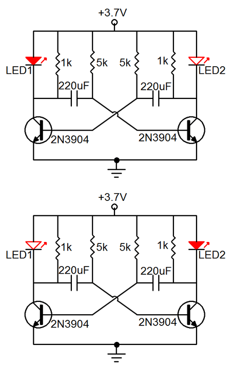
Many of my friends asked me for automatic on off led circuit or led flashing circuit so here I’m going to post a Astable multivibrator-2 LED flashing circuit.
It is a simple astable multivibrator circuit using 2LED (here i used red LED), two NPN small transistor 2N3904 for switching. Here other small NPN transistor can be used, including 2N4401, 2N2222 or PN2222. Supply voltage is +3.7V to +5V or if you want to supply a larger volt then add a required resistor series connected with 2 LED’s. I recommend to use +3.7V for best result . for +3.7V you can use a battery of mobile phone.
The 5K ohms resistor and the 220uF capacitor determines the LED on time(flashing) for each side. You can experiment by changing the 5K & 220uF value.
Pin diagram of transistor 2N3904:
Circuit diagram of Astable multivibrator with 2 LED:
 |
| Fig: Astable multivibrator-2 LED flashing circuit Circuit diagram |
The 5K ohms resistor and the 220uF capacitor determines the LED on time(flashing) for each side. You can experiment by changing the 5K & 220uF value.
Pin diagram of transistor 2N3904:
 |
| Fig: 2N3904 Pin Diagram |
Astable multivibrator-2 LED flashing circuit,2N3904,3.7V
 Reviewed by Shuvojit Das
on
6:57 AM
Rating:
 Reviewed by Shuvojit Das
on
6:57 AM
Rating:


You really should have series resistors with those LEDs. Or perhaps place them in series with the 1k resistors.
ReplyDeleteLook at the supply voltage (+3.7v).
DeleteAt this voltage LED's no need any Series Resistor. And if you remove those parallel resistors, there will not a big problem will happen. If you use higher supply voltage then use appropriate resistor with LED’s in series. Like, for 6V use 220 ohm resistor with both LED’s.
Thanks for your comment buddy.
Keep playing with electronics :)
please tell me how to design above circuit.its mean is at first i have nothing and then somebody requires design this circuit,i must choose supply voltage,bjt,resistor values,capacitor values.they give T(period).i will calculate how.Please help me.If you have idea,ebook or book about it,please send me.Thank you very much.
ReplyDeletedude what is the procedure if i want to include more LED s? Like i want to decorate a photo with flashing leds.
ReplyDeleteI have 50 led to left side of the photo and another 50 at the right side. I just want to flash these with proper brightness. Can you please suggest the diagram ?
dude what is the procedure if i want to include more LED s? Like i want to decorate a photo with flashing leds.
ReplyDeleteI have 50 led to left side of the photo and another 50 at the right side. I just want to flash these with proper brightness. Can you please suggest the diagram ?
I would definitely move the 1K ohm resistors so they are in series with the LEDs and not in parallel. The parallel resistor is just a current waster while it is always necessary to use a series current limiting resistor when driving LEDs. That is the most inexpensive way to guarantee the correct current through the LED. Remember LEDs are current driven devices not voltage driven devices.LED have a non linear voltage vs current curve and are easily destroyed.
ReplyDelete